
Page 9 - e3328g
P. 9
Roller Guide RA Series
4. Basic Load Rating and Rated Life
Basic dynamic load rating that expresses load capacity is established by ISO standards (ISO14728-1) for linear
guides. With basic dynamic load rating, direction and size do not fluctuate so that rated fatigue life is 100 km.
Load rating for NSK Linear Guides complies with ISO standards. With the RA series, dynamic load rating is the
same in both the vertical and horizontal directions (4-way equal load specs.). Rated fatigue life L is calculated by
the following formula when load F is applied to the roller slide in the horizontal or vertical direction only.
● This life formula is different from that for linear guides with ball rolling elements. Table 4 Load factor fw Load factor
● fw is load factor. Refer to the respective value from the following table 4 as a 1.0 – 1.5
Impact and/or vibration 1.5 – 2.0
guideline according to potential vibration and the impact of the machine in No impact and vibration from the outside 2.0 – 3.0
which the linear guide is used, and select the load factor. With impact and/or vibration from the outside
With heavy impact and/or vibration from the outside
( ) L = 10 0 ×
C 130 (km)
fw• F
Load applied to the linear guide (ball slide load) comes from various directions up/down and right/left directions
and/or as moment load. Sometimes more than one type of load is applied simultaneously. Sometimes volume and
direction of the load may change.
Varying load cannot be used as it is to calculate life of linear guide. Therefore, it is necessary to use a hypothetical
load to ball slide with a constant volume, which would generate a value equivalent to an actual fatigue life. This is
called “dynamic equivalent load.” For actual calculation, use the loads of Table 5.
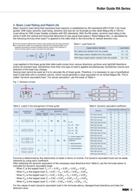
Fig. 7 Direction of load Mp My
Fr
Mr
Fs
Table 5 Loads in the arrangement of linear guide Table 6 Dynamic equivalent coefficient
Loads necessary to calcurate dynamic equivalent load Dynamic equivalent coefficient (1/m)
Pattern Arrangement of Load Moment load Dynamic equivalent load Model No. εr εp εy
linear guide
Up/down Right/left Rolling Pitching Yawing RA15 High load type
(vertical) (lateral) RA15 Super-high load type 105 95 95
RA20 High load type
RA20 Super-high load type 105 70 70
RA25 High load type
1 Fr Fs Mr Mp My Fr =Fr RA25 Super-high load type 79 74 74
RA30 High load type
RA30 Super-high load type 79 55 55
RA35 High load type
Fse =Fs tanα RA35 Super-high load type 71 64 64
RA45 High load type
Fre =ε r Mr RA45 Super-high load type 71 50 50
RA55 High load type
2 Fr Fs Mr Fpe =ε p Mp RA55 Super-high load type 56 58 58
RA65 High load type
Fye =ε y My RA65 Super-high load type 56 44 44
α : Contact angle (=45°) 46 53 53
Dynamic equivalent 46 39 39
3 Fr Fs Mp My coefficient 37 40 40
ε r : Rolling direction 37 30 30
ε p : Pitching direction
ε y : Yawing direction 33 34 34
4 Fr Fs 33 24 24
26 28 28
26 19 19
Formula is determined by the relationship of loads in terms of volume. Full dynamic equivalent load can be easily 8
obtained by using each coefficient.
After obtaining the dynamic equivalent of the necessary load directions from Table 6, use the formulas below to
calculate full dynamic equivalent loads.
· When Fr is the largest load: Fe = Fr + 0.5Fse + 0.5Fre + 0.5Fpe + 0.5Fye
· When Fse is the largest load: Fe = 0.5Fr + Fse + 0.5Fre + 0.5Fpe + 0.5Fye
· When Fre is the largest load: Fe = 0.5Fr + 0.5Fse + Fre + 0.5Fpe + 0.5Fye
· When Fpe is the largest load: Fe = 0.5Fr + 0.5Fse + 0.5Fre + Fpe + 0.5Fye
· When Fye is the largest load: Fe = 0.5Fr + 0.5Fse + 0.5Fre + 0.5Fpe + Fye
For the values of each dynamic equivalent load in the formulas above, disregard load directions and take the
absolute value.